
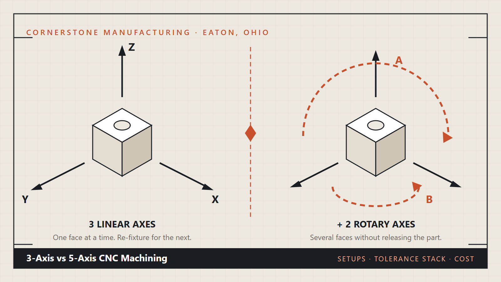
Axis count is the first thing most people ask a machine shop about and the last thing that should decide a quote. What matters is how many times your part has to be unclamped, because every one of those releases starts a new chain of error. Independent sources of error do not simply add: they combine as the square root of the sum of their squares, which is the propagation rule set out in the NIST/SEMATECH e-Handbook of Statistical Methods. That single piece of arithmetic explains most of what follows.
The second thing worth knowing is that the numbers on your drawing are not absolute. Length dimensions are defined at a standard reference temperature of 20 °C, agreed internationally on 17 April 1931 and documented in NIST’s history of the 20 °C reference temperature. Once a tolerance gets tight enough, the room, the coolant and the clamping all move the reading. Axis count is one lever among several.
So the practical questions are narrower than the marketing ones. Does your part have features on more than one face? Do those features have to relate to each other, or only to their own face? Does the quantity justify a dedicated fixture? Get those three right and the axis decision usually makes itself.
The four options, side by side
| Configuration | What it cuts well | Faces per setup | Where the error comes from | Watch-out |
|---|---|---|---|---|
| 3-axis | Plates, covers, housings, anything whose features look one way | 1 | Re-fixturing between faces | Multi-face parts collect a new datum every setup |
| 4-axis (indexed rotary) | Shafts, manifolds, parts with features around a diameter | Several around one axis | Rotary indexing accuracy | Only helps if the features share that axis |
| 3+2 multi-axis | Cross-drilled blocks, angled ports, compound faces | Most or all | One setup, so mostly the machine itself | Fixturing and programming take longer up front |
| 5-axis simultaneous | Sculptured surfaces, impellers, blended 3D geometry | All, continuously | Toolpath and machine kinematics | Rarely needed for prismatic parts, and it costs more to program |
The challenges nobody puts on the quote
Three problems show up again and again on parts that arrive drawn for one machine and end up running on another.
- Tolerance stack-up across setups. Features cut in the same setup relate to each other through the machine. Features cut in different setups relate to each other through however well the part was re-located. A 0.1 mm relocation error is invisible on a general dimension and fatal on a bolt circle that has to line up with a bore.
- Datum drift. Every re-clamp needs a new reference. If the drawing does not say which face is the datum, the shop picks one, and the part that comes back is dimensionally correct against a datum you did not intend.
- Fixture cost hidden inside a low unit price. A three-setup part quoted cheaply usually means three simple fixtures and three chances to load it slightly differently. The unit price looks good until the first article is measured.
What 3-axis actually does well
A great many machined parts are prismatic: a plate, a cover, a bracket, a housing. All the features look one way, the part is held once, and a 3-axis mill cuts everything it needs to. For that part, more axes buy nothing. They add programming time and machine rate to a job that was already going to be right the first time.
The honest test is simple. If you can hold the part in one orientation and reach every feature on the drawing, three axes is the right machine, and any quote that insists otherwise is selling you capacity rather than a part.
What the fourth axis buys you
A rotary axis turns the part between operations, so features spaced around a diameter are cut without releasing it. Shafts are the obvious case: turn the diameters, then index the part to cut a keyway, a cross hole and a flat, all referenced to the same centreline. That reference is the point. The keyway is now square to the journal because the machine never let go of it.
A fourth axis helps only when the features share the rotary axis. Features on a face at right angles to it still need another setup or a tilting head.
3+2 versus full 5-axis simultaneous
These two get sold as one thing and behave very differently. In 3+2 the two rotary axes position the part at a fixed angle and then lock, and the cut happens on three linear axes. It is precise, straightforward to program and covers most industrial work: cross-drilled manifolds, angled ports, compound mounting faces.
Full 5-axis simultaneous moves all five while cutting. That is what a turbine blade or an impeller needs, and what a bracket does not. If your part is prismatic, simultaneous motion adds programming and verification cost without changing a single dimension on the print.
The tolerance stack, in numbers
Take a part whose bolt circle must relate to a bore within 0.10 mm. Cut both in one setup and the error is the machine’s own positioning error, call it 0.02 mm. Cut them in two setups and the relocation error joins in. If relocation contributes 0.06 mm, the combined figure is not 0.02 plus 0.06. Following the propagation rule above, it is the square root of the sum of the squares, which lands near 0.063 mm.
That is still inside 0.10 mm, so the two-setup route works. Add a third setup and the same arithmetic pushes past the limit. This is why the answer to “how many axes” is really an answer to “how many setups can this tolerance afford”. Numbers here are worked examples to show the method, not a specification for your part.
Where the extra axes are worth paying for
Pay for more axes when the part has features on several faces that must relate to each other, when the geometry is genuinely three dimensional, or when the quantity is high enough that removing setups removes labour on every piece. Those three cases repay the programming time quickly.
Do not pay for them to buy general accuracy. A well fixtured 3-axis job holds a close tolerance perfectly well. What multi-axis removes is not error in a feature: it is error between features cut at different times.
How to decide which one your part needs
Work through it in this order and the choice falls out. Count the faces that carry features. If it is one, three axes. Ask whether the features that must relate to each other can be reached without unclamping. If they cannot, you are choosing between a fourth axis and a smarter fixture, and either may be right.
Then check the geometry. Curved, blended, continuously varying surfaces need simultaneous motion. Flat faces at angles do not: they need positioning, which is 3+2. Finally, look at the quantity, because a setup you pay for once is a different decision from a setup you pay for five hundred times.
If that leaves you unsure, that is the normal outcome, and it is the conversation worth having before the drawing is finished rather than after the first article is measured.
Send the print and we will tell you how many setups it needs and why, including the cases where the cheaper machine is the right one. Start at request a quote and a person who runs the machines reads it.
Frequently Asked Questions (FAQs)
Is 5-axis machining always more accurate than 3-axis?
No. A 5-axis machine reduces the number of setups, which reduces error between features cut at different times. The accuracy of any single feature comes from the machine, the tooling and the fixture. A well held 3-axis job holds a close tolerance on an individual feature as reliably as a 5-axis one.
What is the difference between 3+2 and full 5-axis?
In 3+2 the two rotary axes position the part at an angle and lock, then cutting happens on the three linear axes. In full 5-axis all five move during the cut. 3+2 suits angled faces and cross-drilled features. Full simultaneous motion suits curved and blended surfaces such as impellers.
Does 5-axis machining cost more per part?
The machine rate and the programming time are higher, and removing setups reduces handling and fixture cost. Which side wins depends on the part and the quantity. On a multi-face part in reasonable numbers, fewer setups usually wins. On a simple prismatic part it does not.
How do I know how many setups my part needs?
Count the directions your features face and ask whether a single clamping can reach all of them while leaving something to hold. Any feature that cannot be reached without releasing the part adds a setup, and each added setup adds relocation error to every dimension that spans it.
Should I specify tolerances differently for a multi-setup part?
Yes. Mark the tolerance that actually matters and leave the rest at a general default, and use a fit code where a feature has to mate with something. That tells the shop which relationships must survive a setup change, which is the information it needs to choose the right machine.