
Capability
3D machining & assembly
Sculptured surfaces machined from solid, not built up from flat cuts, and then fitted together with the parts they mate to before anything ships. A flange, a gasket and its mating flange leave here as one working joint, not as a box of parts and a hope that they line up on site.
Interactive
A real bolted joint, going together
This is the same flange from the part library, its gasket, and its mating flange, shown as the five things that actually happen when the joint is installed. Load it once and scrub back and forth through the sequence for yourself.
The same sequence, in words
If the model above has not loaded, or you would rather read it, here is the exact sequence it shows.
-
Lower flange located
The machined face sits on the mating spigot. Bore and bolt circle were cut in one setup, so the holes line up without reaming on site.
-
Gasket set on the raised face
The raised face is finish-faced flat within 0.05 mm and left at a controlled roughness, which is what lets a gasket seat without a leak path.
-
Upper flange brought down
The two faces close square because both were faced concentric to the same bore, not clamped straight on assembly.
-
Bolts through the joint
Six bolts drop through a 90 mm bolt circle held to a true position of 0.1 mm. Nothing is drifted or opened out.
-
Joint drawn up
Bolts are pulled up in a crossing pattern so the gasket compresses evenly. The map below shows that order.
Interactive
The bolt-up order, mapped
Six bolts on the flange's own Ø90 mm bolt circle. Step through the order below and watch it cross the circle instead of walking around it.
Torque sequence map
A crossing, star-shaped order: 1, 4, 2, 5, 3, 6.
Not started. Press Play or Next to begin.
Crossing beats going around. Tightening in the crossing order above squeezes the gasket down evenly from all sides at once. Going 1, 2, 3, 4, 5, 6 around the circle lets one side compress before the opposite side even starts, which can pinch the gasket unevenly or leave the joint slightly cocked.
Illustrative No torque figure is shown here on purpose: the real number depends on the bolt grade, the gasket and the flange class specified on your drawing, and it comes from that specification at quote, not from a generic chart.
Interactive
Every part in the assembly, on its own
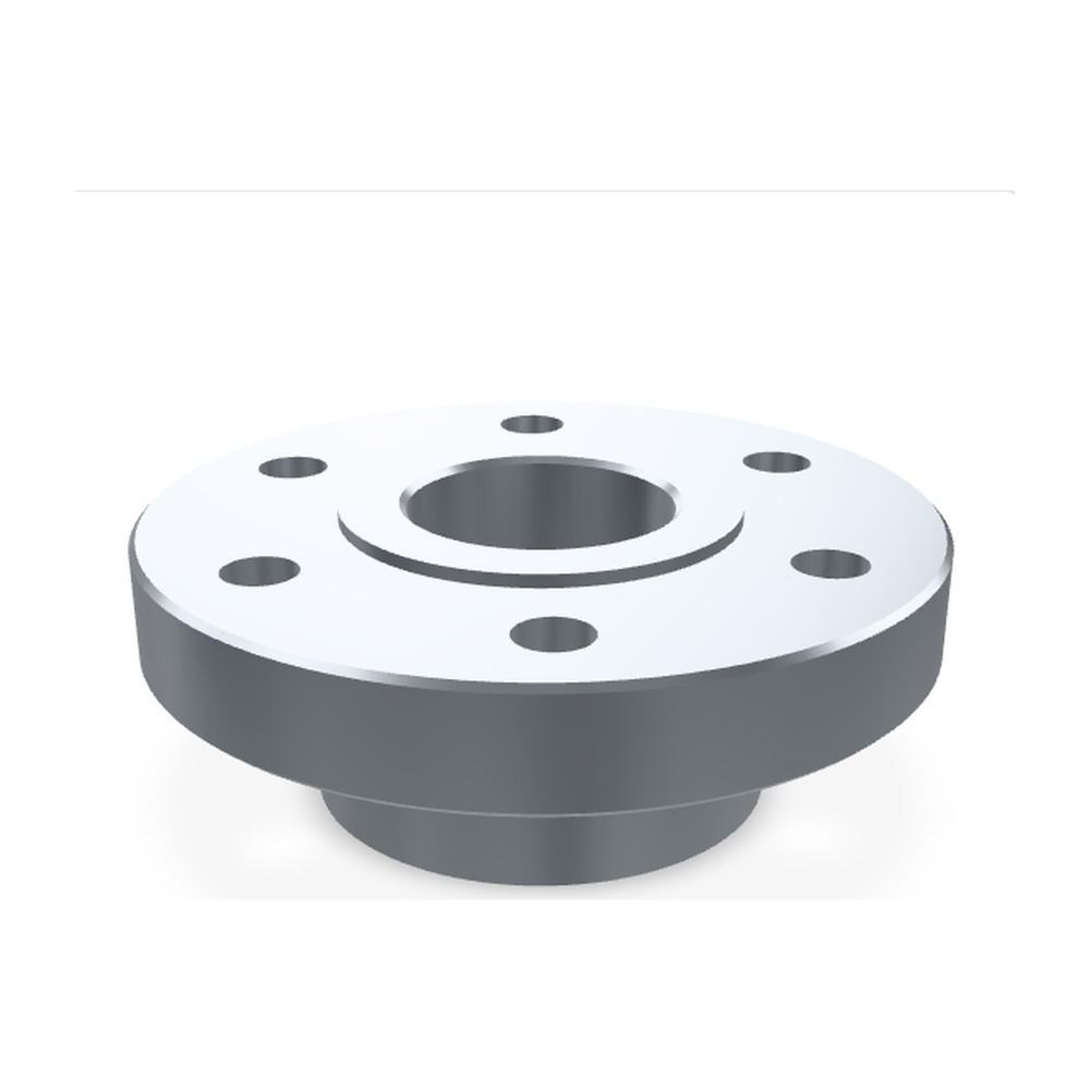
The flange that carries the joint, the manifold block a sculptured internal passage relies on, and the bracket that shows the same fit-to-mate thinking on a milled part rather than a turned one. Switch between them below.
In practice
What “assembly” means here
On a job like this, the flange and its mating flange are not machined to two independent prints and left to see if they get along. They are machined to fit each other: the same bore size, the same bolt circle, the same face flatness, cut with the mating part in mind from the first setup.
- Machined to fit each other. Not just to a tolerance band in isolation, but to the part it has to close against.
- Checked as a set. The parts are proved together, not signed off individually and hoped into agreement later.
- Shipped as one item. What arrives is the working joint, not a kit of pieces and an instruction to figure it out.
See it built out further
This page shows one joint. The full interactive manufacturing experience goes further, with exploded views that pull an assembly apart part by part and a section cut that shows what is happening inside a bore or a port.
Questions we get asked at quote
How is this different from just machining the parts separately?
Machining them separately treats each print as its own job with its own tolerance stack. Machining them as an assembly means the mating dimensions are set against each other from the start, so the fit is designed in rather than discovered on site.
How do you know two machined parts will actually fit together?
By checking them as a set before they ship, not only against the drawing but against the part they mate to. A flange and its mating flange get proved together for exactly that reason.
Can I get an assembly drawing, not just individual part prints?
Yes. Design and engineering is done in house in SolidWorks, so an assembly can be modelled and drawn as a set, with each part's print referencing the same datums as the others.
What if I only need one part from the assembly, not the whole set?
That is a normal request too. A part designed to mate with something else machines the same way whether you order the whole assembly or just the one component.