
Capability
4-axis & multi-axis
Features on more than one face of a part, cut without unclamping it in between. Fewer setups means fewer chances for one face to drift out of position relative to the others.
The engineering point
A new setup is a new datum
Every dimension on a print is measured from somewhere: an edge, a bore, a face. That reference is the datum, and the machine only knows where it is because the part is sitting in a known position in the fixture. Unclamp it and put it back in for a second setup, and it goes back in at a slightly different position: the fixture repeats, but not perfectly. Any feature cut in that second setup is now located relative to a new datum, so its position error adds to whatever the re-fixturing introduced.
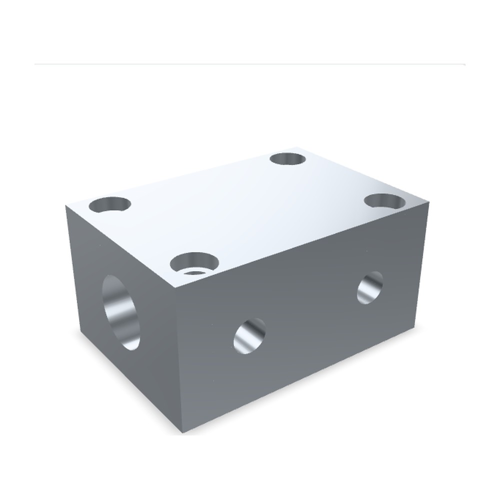
This manifold block is the case that makes it concrete: a main bore, two cross ports on a different face, and mounting holes on a third. Cut on a 3-axis machine, that is at least three setups, one per face. Cut with a 4th axis or 3+2, every feature stays referenced to the same datum the whole time, because the part never leaves the fixture. Drag it, and tap a numbered callout to see what each intersection has to hold.
- 3-axis. The tool moves in X, Y and Z. To reach a second face, the part is physically flipped and re-fixtured.
- 4-axis. A rotary axis, usually called the A-axis, indexes the part around one axis while it stays clamped in the same fixture.
- 3+2 multi-axis. A second rotary axis lets the head tilt to a compound angle, then cut normally from that new orientation, again without moving the part.
Interactive
The setup comparator
Choose how many faces of a part carry features, and which machine configuration is doing the work. The maths behind the tolerance stack is explained under the tool.
Setups, side by side
Same part, three ways of holding it.
1 face 5 faces
Machine configuration
Relative handling time Illustrative
A relative index only, scaled against the most setups this tool can show. Your real handling time comes from your fixture and your part.
…
…
The honest version
When you do not need multi-axis
Being straight about when the simpler route is the right one is the whole point of a shop that quotes its own work. Multi-axis earns its keep when it removes setups that would otherwise cost you accuracy. It does not always.
- One face carries all the features. If nothing is being cut on a second face, there is no stack to protect and no setup to save.
- The part is a true one-off. A couple of manual re-fixtures on a 3-axis machine can cost less in total than programming a rotary setup for a single part.
- The tolerance between faces is loose. If the drawing allows a general tolerance band between features, the relocation error from an extra setup may not matter functionally.
- The geometry is simple stock. A flat plate with through features is already fully reachable in one 3-axis setup.
Questions we get asked about setups
What actually is a "setup" in machining?
One setup is one time the part is clamped into the machine before the program runs. Every unclamp and re-clamp, for any reason, starts a new setup with its own small positioning error relative to the last one.
Is 4-axis the same as 5-axis?
No. A 4-axis machine adds one rotary axis, usually called the A-axis, to a 3-axis mill, so the part can be indexed around that axis without unclamping. 3+2 multi-axis, sometimes marketed as 5-axis positioning, adds a second rotary axis so the head can tilt to a compound angle and then cut normally from that new orientation, still without moving the part.
Does more axes always mean a tighter tolerance?
No. It means fewer setups, and fewer setups means less accumulated relocation error between features. That is a different thing from tightening the tolerance on any one feature, which is a question of process control within a single setup. The comparator above shows the difference.
Do I need to specify 4-axis or 3+2 by name on my drawing?
No. Tell us which features have to stay related to each other and leave the setup strategy to the shop. That is what the quote is for: it is reviewed by the person who will decide how to hold the part, not read off a spec sheet.